
Forward to the Past with the FT101Z
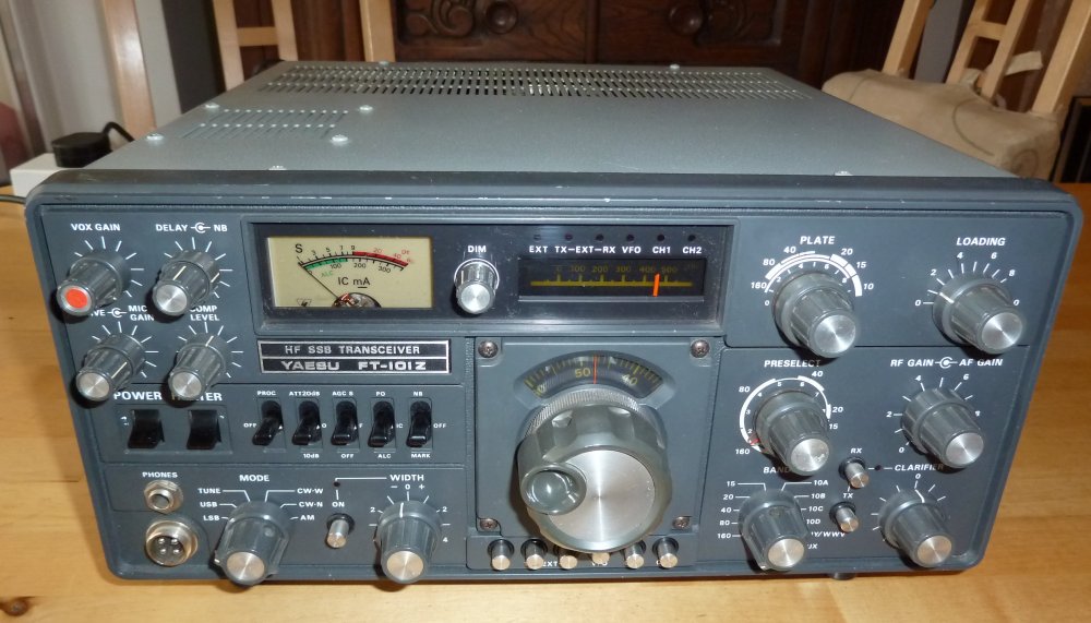
Ahh 1979, when Russia was threatening atomic war, inflation was rampant and there was an energy crisis. How times have changed! I used to look longingly at the adverts in radio magazines for wonderful rigs that seemed completely unobtainable, well it seems if you wait long enough good things do happen. I came into possession of a 1979, FT101Z recently. Wow, never thought I’d own one of those. Ok it was a bit sick, so it went on the shelf, where it kept looking at me sadly, so I thought it was time to get it on the air again.
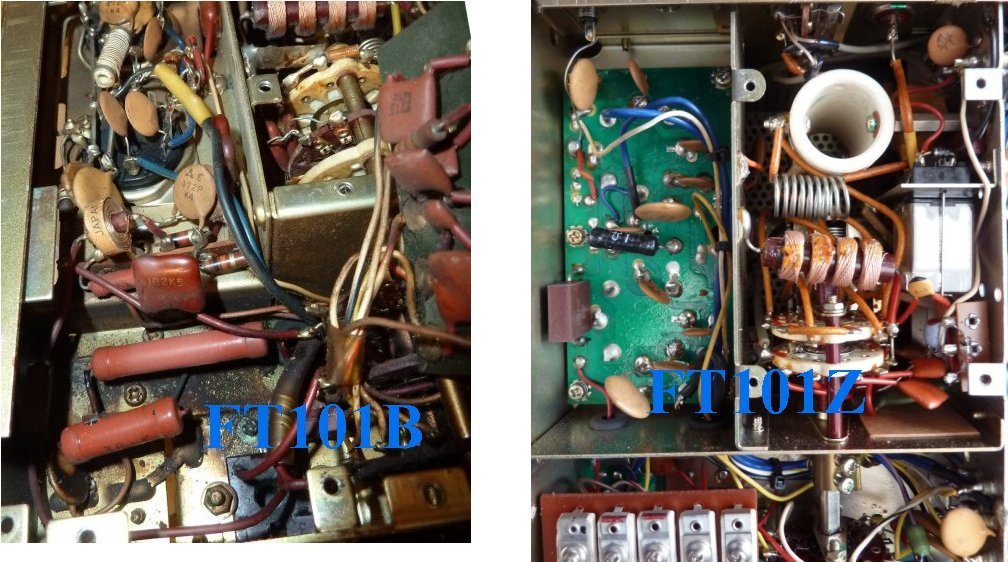
With the covers off, the first thing I noticed is how much the technology moved on compared with my 1975, FT101B from 4 years earlier. The ‘Z’ uses a lot more FETs as well as great improvements to the IF filtering. There is far less point to point wiring, with components placed on small PCBs.
I powered it up slowly to give the electrolytic capacitors time to reform. At full mains voltage all looked well in the power supply section and the voltages measured correctly. When the AF volume was increased there was of loads of noise and crackling. All the switches were intermittent and the potentiometers all crackled when turned. This is to be expected when a radio hasn’t been used for a long time and a good dose of Servisol spray up all the controls fixed most of those problems.
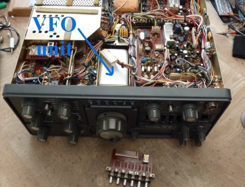
However there was still a lot of receive noise and instability on all bands, so I suspected the VFO had a problem. It’s a self contained unit in a screened box but getting it out of the set isn’t easy.
I finally extracted it and got it apart only to find the whole thing is covered in brown rubberised goo. A look at the circuit shows there’s one tantalum capacitor and they are notorious for failing.
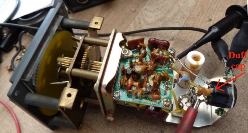
I removed it and it measured 27pF instead of 0.33uF. I replaced it with a 0.47uF ceramic and the output was much more stable.
Getting it back in the set was another challenge. The small fiddly screws, which fix several earth straps to the VFO, keep dropping into the set when you try to fit them. And the 2 wire ended lamps that illuminate the dial are a pain to get back in their grommets. Powering the set up again there was no VFO noise and the set tuned nicely and stayed on frequency. Slight adjustment brought the scale readings very close to the measured frequency. The VFO tracked the scale within about 1KHz, across its whole range of 5 to 5.5MHz. So I hadn’t messed up anything major.
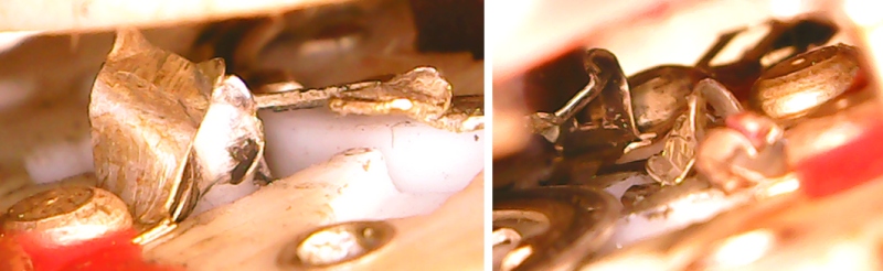
I tried the set on transmit but there was a serious problem on the lower frequency bands, where it was not possible to tune up the power amplifier. The band change switch didn’t feel right and a close look at the wafers in the PA section showed a mess. The wiper seemed to have jammed at some point and turned sideways, mashing up all the contacts on the way round. Note: the 700V HT stays up for quite a while after switch off, so discharge it at the PA valve anodes with an insulated resistor before touching anything.
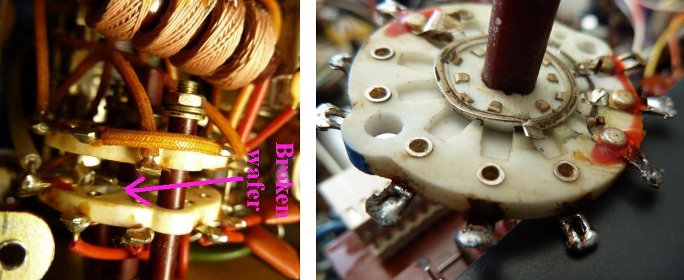
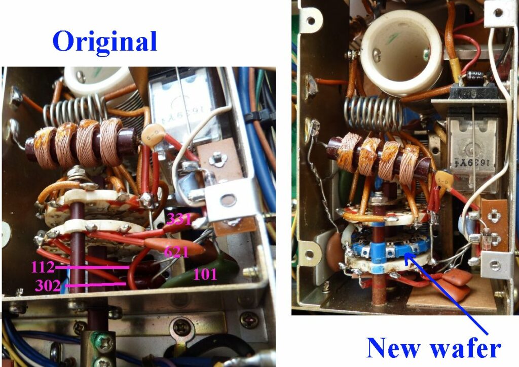
Getting the wafer out was a big job as the components are wired point to point in the PA to keep the lead lengths short. I took loads of photos to give me a clue as to where they all went on reassembly, as well as drawing pictures.
The wafer was beyond repair but in the junk box I had a switch with the same size wafers which also had 12 positions.
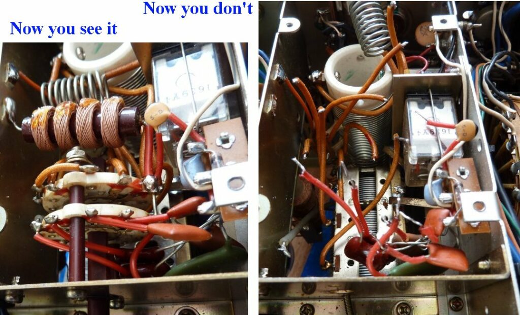
The original is ceramic and this is plastic but it should be OK, so long as we don’t get a flash over. The biggest problem is finding space to get an extra wafer in. I drilled out and removed all of the broken switch contacts. New stand off spacers had to be made and some of the capacitors moved to make space. Small squares of fibreglass board were glued to the metal sides to provide extra insulation for these components.
I tentatively powered it up and there were no fireworks – phew.
The radio was set to transmit and the bias adjusted to give 50mA when idling. The manual’s tune up instructions were followed, starting on the 160m band. The set now gave some power out and the PA could be peaked using the preselect, plate and load controls. The labelling of the controls seems only a rough guide and the actual settings were quite a bit different, especially the load control, which never seem to go beyond 3. Not sure why as the valves look like the original GE ones, so neutralising shouldn’t have changed.
The manual sets the anode current to 150mA max, as this is continuous, to stop the valves being destroyed by excessive dissipation. I found that the power out at this current dropped from 50 watts on the LF bands to 30 on the higher bands.
I used the radio for the Fareham club’s CW practice on 28.35MHz. I could get 100 watts out with the drive turned up. Of course the anode current is much higher but it’s not continuous duty so the valves can take it.
I used the radio on the Horndean club’s nets on 1.95MHz and once again I could get 100 watts out with the drive up, although I only need 50 watts into the ATU to get +14dBW (30W) at the antenna.
In both cases the narrow (600Hz) CW filter and the variable IF width was great on CW. The set performed very well and hardly drifted at all over more than an hour CW session. The relay clicking is rather loud and distracting using the VOX, so I just used the MOX.
The receive audio is very nice and transmit audio reports on SSB were good too. Once again with the drive turned up you can get over 100 watts on all bands.
The VFO takes some getting used to, showing a reading of 450 for 1.95MHz, (1.5 MHz plus 450KHz). Of course you have to retune the PA for each band you use but I’ve printed out lookup table, so not a problem. There’s no noise reduction or bandscope or fancy computer interfaces of course. What you get is a repairable, well engineered, beautifully made radio that exudes quality. What more could you want?
Cheers Mike – M0CAA