Return to Members Interests Page

Chris G8JFJ

presents his

Precision tachometer & dwell meter


Front panel

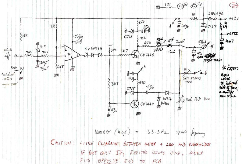
This precision tachometer & dwell meter box originally intended for adjusting petrol engines, with an optical adaptor wand that was constructed retrospectively to allow use of the tachometer function with a diesel engine.
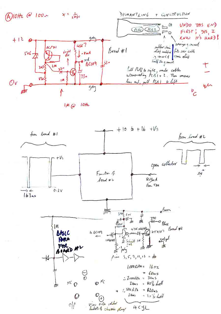
The key improvements claimed over commercially available kit are:

a) greater accuracy;
b) proper independence of the dwell function from engine speed and supply voltage variations; and
c) low speed FSD which is switchable for different numbers of cylinders in the engine
to give good definition of the engine idling speed and stability.

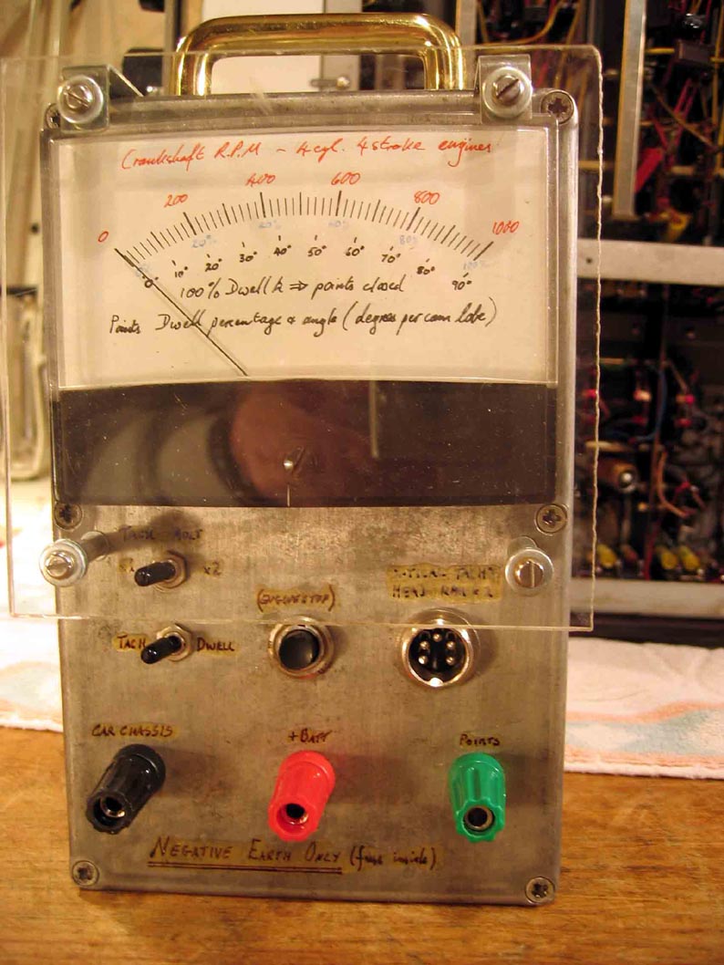
In service with a petrol car, the tachometer & dwell box has three connections to the car:
chassis, +12V and points. For use with a diesel car, only chassis and +12V are connected because there are no points.
The adaptor wand plugs into the tachometer & dwell box, and a conventional torch is carried piggy-back.
The beams of both the torch and the adaptor wand are arranged to focus on a strip of silver foil stuck somewhere on the periphery of the engine flywheel.
The strip can be anything from 1” to 3” long. A solid RPM reading is obtained, no problem.


First consider the above circuit.
This shows the contents of the main tachometer/dwell box,
taking its input signal from the contact breaker points of a conventional Kettering ignition system.

The car manufacturer specifies the percentage of time the points should be closed,
either as a “% dwell” value or as a “degrees dwell” value.
Hence the dual scaling on the meter.

The points gap is adjusted to give the specified dwell value.
When the points are closed, the PD across them should be 0V.
In reality, some 300mV is often measured. When the points are open, the PD
across them is somewhere between 11V and 14V, assuming a 12V electrical system.
The transitions from open to closed, and (especially) from closed to open have
huge overshoots. !!!!

WARNING: the points voltage can give you a big electric shock!!!!

The measurement electronics must disregard these transient conditions and must not be damaged
by the overshoot voltages.

This circuit can be used with the engine running normally, or with the engine being cranked with the coil
disconnected. This is achieved by using a circuit that will trigger either from a voltage point,
or from a suitable resistance change when the circuit is unpowered.
Think of the 741 op-amp as an infinite gain differential amplifier.
When the coil is powered, one 741 input is tied to a reference voltage of [6.8 / (6.8 + 12)] * 12V = 4.3V.
The other input is tied to the points via buffering network comprising of two 7.5k resistors,
a 10V zener and a 10nF capacitor. This passive network stops harmful or confusing surges reaching the 741.
When the coil is powered and the engine is running, the circuit will trigger at a
points voltage of 4.3V, which seems OK.
When the coil is not powered and the engine is cranking, the circuit will trigger
at a points resistance of R, where R / (R + 15k Ω * 12V = 4.3V.
This means the circuit will trigger at R = 8.4k Ω , which seems a reasonable compromise.

Leaving the 741 is a cleaned-up inverted copy of the points voltage,
accurately preserving its mechanical mark:space ratio whilst ensuring a high level p-p output.
The string of three 1N914s ensures that both CV7440 Silicon NPN transistors switch cleanly at the
point where the 741 output is at 3x 600mV (1N914 drops) + 600mV (CV7440 B-E junction drop) = 2.4V.
This is well into the linear region of the 741 output, to promote solid switching free of fuzzy
edges and rounded corners.
Of interest, the CV7440 (BFY51) is a highly useful general purpose transistor.
It’s old and cheap but very tough, ideal as a low power driver.

The top CV7440 acts as an inverting DC amplifier and driver for the meter,
when the toggleswitch is set to “points dwell”.
The time constant for the measurement is set by the 47µF across the meter winding.
If this capacitor is too small, the meter needle flickers annoyingly.
If too large, it becomes difficult to adjust the engine because the meter is unresponsive.
The DC feed to the top CV7440 is regulated at 7.5V by a zener diode, to protect against
supply voltage variations.

The bottom CV7440 acts as a pulse-counting discriminator for the points signal,
giving an output to the meter which represents the frequency of its input signal.
The circuit uses the CV7440 as an AC amplifying pump which feeds a pulse-doubling meter
rectifier when the toggleswitch is set to indicate engine speed (tachometer function).
The zener diode clamps the collector voltage to 7.5V, to ensure reasonable immunity from supply voltage fluctuations.


Now consider the above circuit.
This shows the optical “diesel adaptor” wand.
It comprises two little PCBs stuffed inside the body of an old torch, as follows.

The circuit shown in red at the top of this scan is the “input” board, designated PCB1.
It uses an OCP71 Germanium PNP phototransistor, which in reality is an OC71 with the black paint scraped off.
This device is mounted in place of the original bulb.
The mechanism was carefully adjusted such that the OCP71 was at the centre of focus,
and then the adjustable focus ring was locked in position with araldite.
Note #1: Not having a genuine OCP71 to hand, I used an OC71 which had translucent
jelly inside its glass envelope to support & cool the Germanium chip.

Other samples of OC71 were found to use a white paste material,
looking very similar to heatsink compound. A transistor of this type would not
have been suitable, as (obviously) no light would have reached the semiconductor
chip even with all the black paint scraped off!

Note #2: The method of focusing the beam was to stare into the front of the reflector and adjust the focusing ring to give the clearest view of the Germanium slice.
The circuit of the input board is extremely simple.
A 5.6V zener diode stabilises the operating condition for the OCP71.
The OCP71 phototransistor is used as a crude amplifier, biased more or less into its linear region to optimise the photosensitivity.
The output is AC coupled from the OCP71 collector to a BC109,
which is configured as a super-gain amplifier switch.
This Silicon NPN device has an extremely high HFE value of maybe 600,
so the output of PCB1 output consists of a reasonably well squared-off signal to feed PCB2.
Why are the devices on PCB1 AC coupled rather than DC coupled?

Answer #1: because I was far more concerned with the position of the
up-down edges than the absolute DC levels at the top & bottom.

Answer #2: Germanium devices have appalling stability of their characteristics over time and over the temperature range.
I needed to make sure the overall design would be as immune as possible from drift in the OCP71 characteristic.


inner workings

The circuit shown in black at the bottom of this scan is the “output” board, designated PCB2.
It is fed from the output of PCB1.
The basic idea for PCB2 is shown in a block on the left.
A 1N4148 series diode is used as a 600mV level shifter to ensure that an ensuing Schmidt trigger will give jitter-free slicing.
Now moving to the detail circuit diagram to the right, we can see that the Schmidt trigger
is a CMOS device fed from a regulated 6.8V line. The output from the Schmidt device is fed
into a ZTX107 which acts as a simulator of mechanical points.

The ZTX107 is similar to a BC109, but it has slightly lower gain and is more robust - very suitable for service in this output driver role.
The ZTX107 has an input series 1N4148 diode acting as a level shifter to make sure it switches when the Schmidt
trigger output is at 600mV (1N4148 drop) + 600mV (ZTX107 B-E junction drop) = 1.2V. This is ideal to achieve the most decisive switching.

Important note: The optical adaptor wand makes no attempt to modify the mark:space ratio of the optical signal it reads from the silver foil whizzing round on the engine flywheel rim.
This is because diesel engines have no ignition system, therefore there is no need for any form of dwell metering.
It is however, usually necessary to adjust the idle speed to a greater level of accuracy than for a petrol engine.

Return to Members Interests Page


©2006 - 2009 F & DARC